Pushing the Oric's limits: five experimental extensions for the LOCI board
How a cycle-stepped emulator becomes a hardware test bench — with the ABI, registers and diagrams.
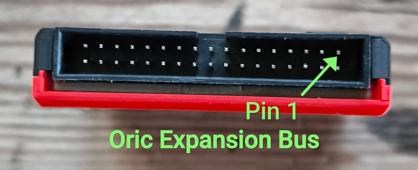
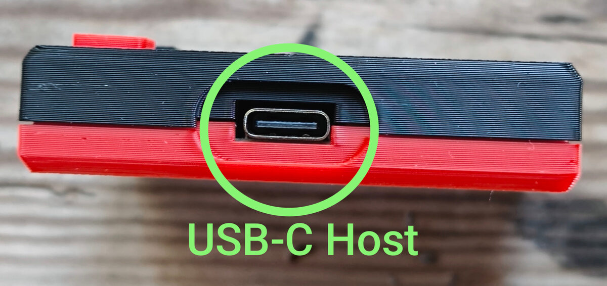
About the photos. The illustrations of the LOCI board come from the official hardware documentation by sodiumlb (loci-hardware) and belong to their author.
- LOCI board, product shots: raxiss.com
- Reseller page: Tindie — 8BitClub
- Development thread: forum.defence-force.org t=2593
1. The hardware context
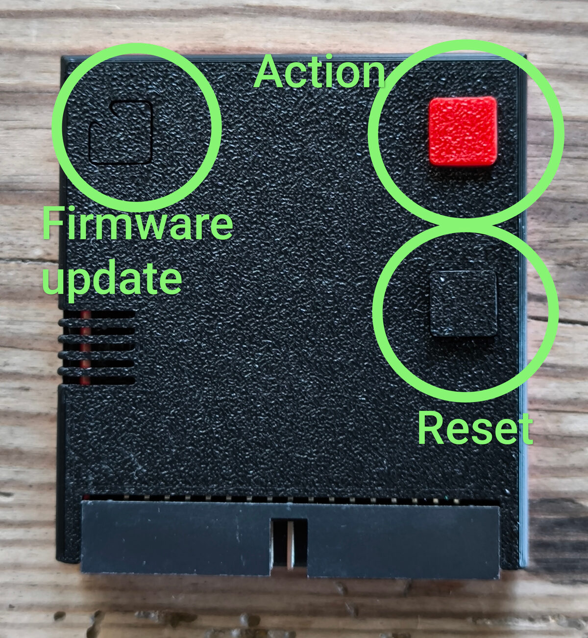
The Oric-1 and the Atmos (1983) are built around a
MOS 6502 at 1 MHz, with a 64 KB address space whose top region
($C000-$FFFF) is occupied by the BASIC ROM. No
hardware multiply, no memory banking, no modern storage: everything goes
through the expansion bus at the back of the machine.
The LOCI board (Lovely Oric Computer Interface) by sodiumlb plugs into that bus. Technically, it is a derivative of the Picocomputer 6502 (RP6502): an RP2040 microcontroller (a Raspberry Pi Pico) acts as a MIA (Media Interface Adapter) that exposes itself to the Oric as an I/O peripheral. It emulates floppy and cassette drives, manages an SD card and acts as a USB host — it is through this USB port that a Wi-Fi modem (a separate dongle, the PicoWiFiModemUSB) or a HID device (mouse, gamepad) plugs in; Wi-Fi is not built into the LOCI board itself. Two addressing surfaces concern us here:
         Oric address space (64 KB)
   $0000 ┌──────────────────────────────┐
         │ RAM                          │
   $0300 ├──────────────────────────────┤
         │ VIA 6522        $0300-$030F  │
   $0310 │ Microdisc WD1793 $0310-$031F │
         ├──────────────────────────────┤
   $0380 │ ACIA 6551 (LOCI) $0380-$0383 │ ← serial console / modem
         ├──────────────────────────────┤
   $03A0 │ MIA (LOCI)      $03A0-$03BF  │ ← 32-byte API window
         ├──────────────────────────────┤
   $C000 │ ROM BASIC       $C000-$FFFF  │ ← bank overlay target
   $FFFF └──────────────────────────────┘
The Phosphoric emulator (cycle-stepped, C11) faithfully reproduces this board, which enables a rare approach: writing the spec of an extension, coding it, and validating it with deterministic tests — before touching the soldering iron. A detail that matters: the author owns a LOCI board, but no Oric. The software bench is not a luxury, it is the only test room.
2. The fastcall ABI — how the 6502 calls the board
Everything rests on a window of 32 registers at
$03A0-$03BF (the MIA). Here is the actual map of the registers used by the
ABI (names faithful to the firmware):
 Offset  Address  Register          Role
 ------  -------  ----------------  ------------------------------------------
  $00    $03A0    CONS_FLAGS        bit7 = TX free, bit6 = RX ready
  $01    $03A1    CONS_TX           console write (UART)
  $02    $03A2    CONS_CHAR         console read (consumes the byte)
  $0C    $03AC    API_STACK         xstack pointer (argument stack)
  $0D    $03AD    API_ERRNO_LO      errno low
  $0E    $03AE    API_ERRNO_HI      errno high
  $0F    $03AF    API_OP            ← WRITE HERE triggers the operation
  $12    $03B2    BUSY              bit7 = board busy
  $14    $03B4    API_A             A return value
  $16    $03B6    API_X             X return value
$18 $03B8 API_SREG 16-bit return (SREG)include/io/loci.h).The call protocol (fastcall) comes down to four steps:
   6502 (Oric)                         MIA (LOCI, µC)
   ───────────                         ──────────────
   1. push args ──► xstack ($03AC)
   2. set A/X (direct parameters)
   3. write op ──► API_OP ($03AF) ───► triggers the handler
                                       ├─ BUSY=1
      poll BUSY ($03B2) ◄──────────────┤  executes
                                       └─ BUSY=0, fills API_A/X/SREG, ERRNO
4. read API_A/API_X ($03B4/$03B6) ◄─ resultEvery still-free opcode value is an entry point for a
new function. The standard operations run from $01 to $98
(clock, open/read/lseek, directories, image
mounting, TAP…). It is in the unused opcodes that our
five extensions live:
  $A7  SET_BANK        16 KB switchable bank        (--loci-bank)
  $A8  STREAM_BANK     asset streamer               (--loci-bank)
  $A9  MATH            arithmetic coprocessor       (--loci-coproc)
  $AA  ACIA_RELIABLE   reliable ACIA mode (seqlock) (opt-in mode)
       + acia_stat_checked : lossless RX handshake  (--loci-acia-rx-nag)
Safeguard by design. Without the corresponding activation flag, the opcode returns
ENOSYS(errno 13) — exactly like an unpatched firmware. Oric software can therefore detect the presence of the extension and fall back on its own routines. The LOCI's default behaviour remains strictly that of the original hardware.
3. Arithmetic coprocessor — $A9
The problem. The 6502 has no hardware multiply, no division and no floating point. Every operation is a software routine: slow, bulky, cycle-hungry. On a 1 MHz machine, a 16×16 multiply runs into hundreds of cycles.
The idea. Delegate the computation to the board's microcontroller, much
faster, through the existing fastcall ABI — a single opcode $A9,
the operation sub-code in API_A, the operands on the xstack, the
result in API_A/SREG.
   ; conceptual example: A×B via the coprocessor
   LDA #<op_mul  : STA API_A     ; operation sub-code
   ... push A, B onto the xstack ($03AC)
   LDA #$A9      : STA API_OP     ; triggers MATH
   ; poll BUSY, then read the 32-bit result in SREG
The implementation. An isolated file,
src/io/loci_math.c (op_math), wired into the dispatch.
Integers, floats, vector operations. Gated by --loci-coproc.
Coverage: 23 deterministic tests (integer vectors, floats, edge
cases). Zero randomness — same inputs, same outputs, the condition of a reproducible
bench.
4. Reliable ACIA mode — $AA (seqlock + ACK)
The problem. The real ACIA 6551 has a well-known flaw: if the 6502 does not read the data register in time, the received byte is overwritten by the next one. At high bit rates — a Wi-Fi modem, for example — bytes are lost, and the link becomes unusable. This is faithful to the silicon, but crippling.
The solution: a seqlock. A receive sequence counter and an acknowledgement on the 6502 side. The byte is only consumed once acknowledged — never lost, even if the read is late or fails.
     Classic 6551 reception (destructive)
     ─────────────────────────────────────
     RX byte1 ──► RDR   (6502 hasn't read…)
     RX byte2 ──► RDR   ✗ byte1 OVERWRITTEN, lost

     Reliable mode $AA (seqlock + ACK)
     ───────────────────────────────
        RXSEQ $0384  (counter, incremented on each presented byte)
        RXACK $0385  (acknowledgement written by the 6502)

     RX byte1 ─► presents, RXSEQ++           consumed := (RXACK == RXSEQ)
     6502 reads byte1, writes RXACK = RXSEQ ─► byte1 acked → advance
RX byte2 ─► presents only if acked ✓ no byte lostThe transmit channel is unchanged (always reliable). State carried
by loci_t (acia_reliable, acia_rx_seq,
acia_rx_presented), opcode $AA, activation via
API_A bit0. Coverage: +7 tests
(test-loci-acia-miss, 13 → 20) — non-destructive DATA, ACK-gated
consumption, multi-byte seqlock in order, and above all
survival of a missed read.
4a. Lossless RX handshake — acia_stat_checked (--loci-acia-rx-nag)
An adjacent refinement, modelled on the real firmware
(feature/acia-rx-lossless). On the real LOCI, the ACIA's /IRQ is
a level signal, not a pulse. We model that level with a "nag": as
long as the byte has not been read (stat_checked
false), the interrupt is re-asserted periodically (default: every
1000 cycles), then goes silent as soon as the 6502 has consulted the
status register.
   RDRF=1 (byte avail) ───┐
                          │  nag: deassert+assert /IRQ every 1000 cyc
   /IRQ  ▁▔▁▔▁▔▁▔▁▔▁▔▁▔▁▔ │  while  RDRF && !stat_checked && RX-IRQ enabled
                          │
6502 reads STATUS ─────┘ stat_checked = true ──► /IRQ silentWithout --loci-acia-rx-nag, the ACIA stays strictly a
6551 (no nag). Coverage in test-loci-acia-miss: nag
observed before acknowledgement, silence after, empty
buffer ⇒ no IRQ.
5. 16 KB switchable bank — $A7 (--loci-bank)
The problem. How do you give more memory to a machine whose space is saturated by ROM?
The solution. Temporarily overlay 16 KB of the board's RAM
(xram) into the $C000-$FFFF window, where the ROM sits.
        $A7 disabled                  $A7 EN | SEL=n
   $C000 ┌───────────┐          $C000 ┌───────────────┐
         │ ROM BASIC │   ─────►        │ xram[n*0x4000]│  overlay (read)
   $FFFF └───────────┘          $FFFF  └───────────────┘
                                       └─ ROM intact BELOW (not overwritten)
xram base = SEL * 0x4000 ; SEL clamped to 0..3 (like mia_set_bank)The key point: non-destructive overlay. The bank takes priority for
reads (and for memory inspection) without ever overwriting the ROM
array. Disabling it restores the machine byte for byte.
The old prototype approach using memcpy + backup was abandoned in
favour of this clean overlay (memory_set_loci_bank() in
memory.c).
Dual mode via reset. Activation through
$A7 EN triggers a reset: the 6502 re-reads its
$FFFC vector from the bank (you can therefore boot
bank code). The hot-swap (used by the $A8 streamer) instead switches
without a CPU reset — an absolute prerequisite for double-buffering.
Coverage: test-loci 170/170 (+4: enable/state,
disable, gated OFF → ENOSYS, SEL clamp 15→3) and an
end-to-end test-loci-bank-e2e.
6. Asset streamer — $A8
The idea. Once the bank is in place, pour data into it
from a file (flash or SD card) in a single
fastcall: lseek(SEEK_SET) + read → 16 KB bank,
with optional mapping in $C000-$FFFF. Oric software can then
go beyond the usable 48 KB: overlays, scenery, levels on demand.
   Double-buffering (beyond 48 KB without a reset)
   ─────────────────────────────────────────────
   $A8 MAP=0 SEL=1 ─► preloads bank 1 (invisible)         ┐ during
   (the 6502 keeps executing/displaying bank 0)            ┘ this time
$A8 MAP=1 SEL=1 ─► switches bank 1 into $C000 (hot-swap, PC intact)Details: API_A bit7 = MAP, bits3:0 = SEL
(0..3 valid; >3 = EINVAL, no clamp
unlike $A7). LIFO xstack arguments
(len, dst, off, fd), write bounded to bank size, return
AX = bytes read. Two read paths: host file and
SD image. Reuses the --loci-bank opt-in.
7. The tearing model — the two-core question
The subtlest extension, and the most intellectually honest.
The question. When you switch a bank while a bus cycle is in progress, what does the 6502 latch? On the single-threaded emulator, the swap is atomic: invisible, the question never arises. But real hardware has two cores; a swap concurrent with a memory access can produce tearing.
The answer: explicitly model the worst case. With
--loci-bank-tearing, a $A8 MAP hot-swap concurrent with a
lost PHI2 bus race makes the 6502 latch open-bus
on the first read of the window (one-shot behaviour),
then the bank takes over.
   PHI2 bus cycle  ─┬─ race won  ─► bank served cleanly (atomic)
                    │
                    └─ race LOST ─► 1st read = OPEN-BUS (latched value)
                                        then  ─► bank   (one-shot consumed)
(reuses loci_mia_serve_lost_sampled + seeded jitter, deterministic)The associated test is self-diagnosing: it first checks the
precondition (the race is indeed lost), then that the model
arms the tearing flag, then that the one-shot is
consumed. An incomplete build now fails on a clear assertion
rather than a cryptic torn != pat[0]. Deterministic (jitter 0): three
clean builds, identical results. test-loci-bank-e2e
8/8.
8. What the exercise teaches
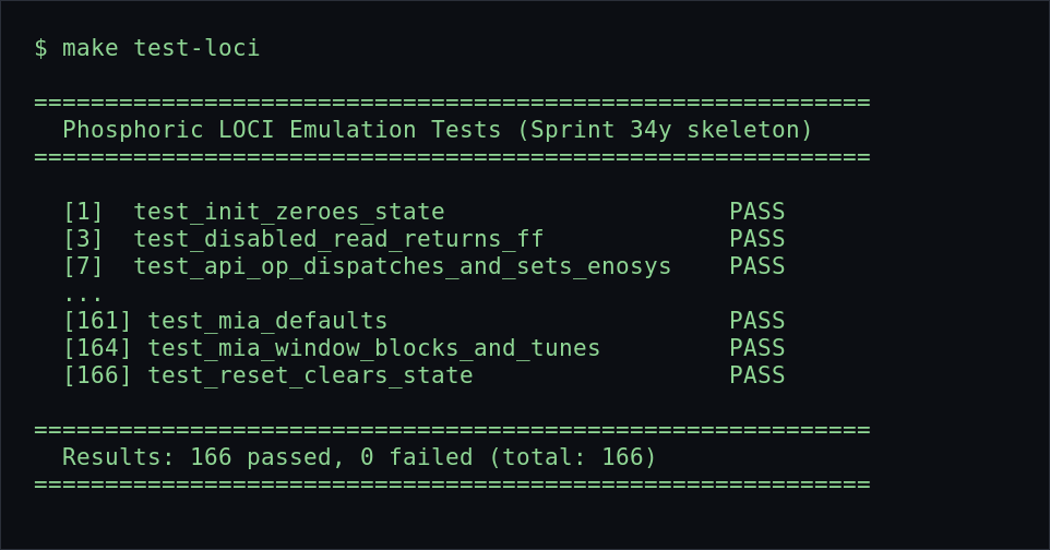
test-loci suite — the headless
prototyping bench. Real output from the stable branch
(main, 166/166); the five extensions bring the total to 170 on the
experiment branch.Five extensions, five minimal additions to an existing ABI,
zero regression on the default behaviour. Each is reversible
(flag-driven), ENOSYS-gated without its opt-in, and backed by
deterministic tests.
The real lesson perhaps lies here: on a 1983 machine, the difficulty is not imagining modern functions, but grafting them without betraying the original behaviour — and proving it before reaching for the soldering iron.
The cycle-stepped emulator stops being a mere playable museum: it becomes a hardware prototyping bench. You write the spec there, you code the extension there, you run the tests there… and the silicon only arrives last, its acceptance sheet already filled in.
The five extensions live on the
experiment/loci-coproc-acia-reliable branch of Phosphoric — opt-in, reversible,
outside the stable release. To be tested, criticised, improved.
Sources & links
- LOCI firmware / hardware (sodiumlb): loci-firmware, loci-hardware, loci-rom
- User manual (FR): LOCI wiki, ceo.oric.org
- Reseller & photos: RAXISS, Tindie
- Development thread: forum.defence-force.org
- Phosphoric emulator: Codeberg · Framagit · GitHub, LOCI documentation on this site